
2GR Swap Cruise Control
Introduction:
This guide can easily be adapted to any 2GR swapped vehicle. I am using my MR2 for this example, but follow the same steps for an SW20, AW11, or any other car you might drop a GR in. There are a few Spyder-specific notes if you are working on one of those vehicles, which is documented here, thanks to Michael Scholten. Michael also helped me with some brief troubleshooting on getting this working on my RAV4, so special thanks to him.
Definitions:
To start off, the only assumption I am making here is that you are using a 3rd generation Sienna ECU from Frankenstein Motorworks with the QOL tune update. If you are using a different ECU, many of the features will be missing and I cannot guarantee functionality.
We will be interfacing with both ECU connectors, the small connector I will be calling “A”, and the large connector I will be calling “B”, followed by the pin number. (I.E. A-11 would be small plug, pin 11).

Inputs needed:
There are a few specific inputs needed in order to satisfy the ECU’s cruise control logic. There are some workarounds for some of these, but they are all important. I would not recommend skipping any of these with a workaround, and will not be covering those here.
Speed Signal
Clutch Input
Brake Input
Cruise Control Switch
Speed Signal:
Toyota uses a 12 volt 4000 pulse per mile speed signal. This appears to be true across all of their cars that use electronic speedometers. Many Toyotas generate an output signal internally to the cluster. Connect this to A-13. You can verify this speed signal is functional by reading speed over OBD2. Most readers have this function built in.
Clutch Switch:
The clutch switch required for this ECU is normally open. This means that there is no continuity when the pedal is pressed, and closed when the pedal is released. Toyota shows this as a normally closed switch on some wiring diagrams, because the “normal” position is with the clutch pedal released. We need to match this same behavior.
If your car does not have a clutch switch, or behaves differently to that above, a suitable switch for any application would be 88280-14030 (Connector: 90980-10906, Terminals: 82998-12340 or Sumitomo 2.3II). This will drop in place into most Toyota pedal assemblies. Wire one side to ground, and the other side to A-35. Note that this is actually listed as “ST-” on the diagram, Marc has changed the function of this input to clutch input. To verify this is behaving correctly, you should see ground at pin B-30 when the pedal is released, and no continuity when the pedal is pressed.

IGNORE THIS, PENDING UPDATE

Brake Switch:
While most Toyota vehicles require two inputs for brake, Marc has reassigned the brake confirmation signal to be the clutch switch input, meaning we only have to have a single brake input for this ECU. Pin A-36 must see 12V when the brake pedal is pressed. The easiest way to accomplish this is to hook your brake light circuit to this pin. If you’re working in an MR2 this will be easy, since your ECU will likely be near your brake lights.
To verify the behavior of this, check for 12V at A-39 when the pedal is pressed, and 0V when the pedal is released.
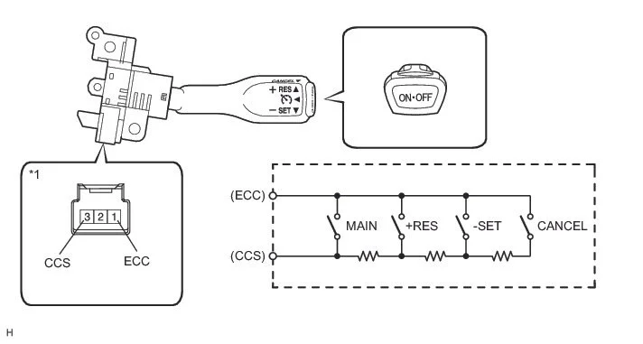
Cruise Control Switch:
Toyota uses a resistor ladder for the cruise switch. Annoyingly the resisors change from time to time. Find a cruise switch that fits your steering wheel and change the resistors accordingly. I got my cruise control switch from a 2013 Sienna. There are only two wires on the cruise switch, and due to the resistor ladder, polarity does not matter here. The resistances should be as follows:
NEUTRAL: 1 MΩ or higher
+RES/Accel: 235 to 245 Ω
-SET/Coast: 617 to 643 Ω
CANCEL: 1509 to 1571 Ω
Main Switch: Below 2.5 Ω
If your resistances do not match, replace the resistors inside of your cruise switch with those above.

These will of course have to be run through your clockspring. Pinout does not matter here, just find two suitable open pins. On the other side, connect one wire to ground, and the other to A-45. Again, pinout does not matter here. To verify this behavior, repeat the above resistance test but between ECU ground and A-45.
Conclusion
If you did everything correctly, you now have functional cruise control. Test this at low speeds and verify that pressing your brake and clutch pedals both cancel the cruise control individually. Test that each function of the cruise switch is correct, and now you’re good to go! The only issue currently is that the 2GR ECU does not have a cruise control light output. If you desire this, it can be accomplished with a CAN module which I will not go into here.