2AR Swap Cruise Control
Introduction:
This guide can easily be adapted to any 2AR swapped vehicle. I am using my RAV4 for this example, but follow the same steps for an SW20, AW11, or any other car you might drop a 2AR in. There are a few Spyder-specific notes if you are working on one of those vehicles, which is documented here, thanks to Michael Scholten. Michael also helped me with some brief troubleshooting on getting this working on my RAV4, so special thanks to him.
Definitions:
To start off, the only assumption I am making here is that you are using a 2nd gen Scion tC ECU. This is the standard ECU from Frankenstein Motorworks. If you are using a different ECU, the pinouts may change but this is largely the same process.
We will be interfacing with both ECU connectors, the small connector I will be calling “A”, and the large connector I will be calling “B”, followed by the pin number. (I.E. A-11 would be small plug, pin 11).
Inputs needed:
There are a few specific inputs needed in order to satisfy the ECU’s cruise control logic. There are some workarounds for some of these, but they are all important. I would not recommend skipping any of these with a workaround, and will not be covering those here.
Speed Signal
Clutch Input
Brake Inputs
Cruise Control Switch
Speed Signal:
Toyota uses a 12 volt 4000 pulse per mile speed signal. This appears to be true across all of their cars that use electronic speedometers. Many Toyotas generate an output signal internally to the cluster. Connect this to A-15. You can verify this speed signal is functional by reading speed over OBD2. Most readers have this function built in.
Clutch Switch:
The clutch switch from our donor Scion tC is normally open. This means that there is no continuity when the pedal is pressed, and closed when the pedal is released. Toyota shows this as a normally closed switch on the wiring diagram, because the “normal” position is with the clutch pedal released. We need to match this same behavior.
If your car does not have a clutch switch, or behaves differently to that above, a suitable switch for any application would be 88280-14030 (Connector: 90980-10906, Terminals: 82998-12340 or Sumitomo 2.3II). This will drop in place into most Toyota pedal assemblies. This is what I used on my RAV4. Wire one side to switched 12V power, and the other side to B-30. Note that this is actually listed as “D” on the diagram, this is the same pin that the automatic models to enable drive. To verify this is behaving correctly, you should see 12V at pin B-30 when the pedal is released, and 0V when the pedal is pressed.
Brake Switch:
The tC as well as most Toyotas since the late 90s uses a two pole brake switch, with one being inverted from the other. If your car came with cruise control you may already have a functional switch. If my RAV4 were to have come with cruise, the switch would be correct.
You will need two signals for this. “STP” needs to see 12V when the brake is pressed and 0V when the switch is released. “ST1- “ needs to see 12V when the brake is released and 0V when the brake is pressed.
There are two ways to accomplish this. Either by using a suitable switch, or by using a relay. I will cover both here.
Switch Method:
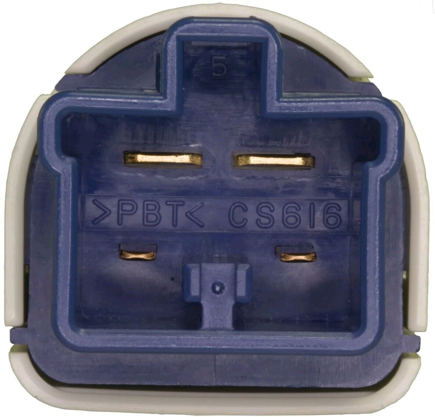
Toyota has many applications with a suitable brake switch. Your car may already have this. If you see the below connector with only the two larger pins, your switch is missing the correct logic. If you see the same connector with all four pins, your switch will work. The top two pins are closed when the pedal is pressed. This is what controls your brake lights. Connect the switched side to pin A-29. If your car came factory wired for this switch, it will be pin 1 on the connector. The bottom two pins are closed when the pedal is released. Connect one side to switched ignition and the other to pin A-31. If these wires are already existing on your car this will be pin 3.
Switch: 84340-06010
Connector: 90980-11118
Terminals: 82998-12480 or Sumitomo 4.8 (Large), 82998-12340 or Sumitomo 2.3II (Small)
Relay Method:
To start, you still need to connect the brake signal to A-29, just like the previous method. If you don’t want to replace the switch, you can use a normally closed relay output activated by the brake signal. For a standard automotive relay connect this to pin 86. Connect pin 87 to ground. Connect pin 30 to a switched 12V source. Connect pin 87A to A-31, just like before. This may be the preferred method when wiring an MR2 when your ECU is a far distance from your pedal.
To verify the behavior of this, check for 12V at A-29 and 0V at A-31 when you have the pedal pressed, and inverted when the pedal is released.
Cruise Control Switch:
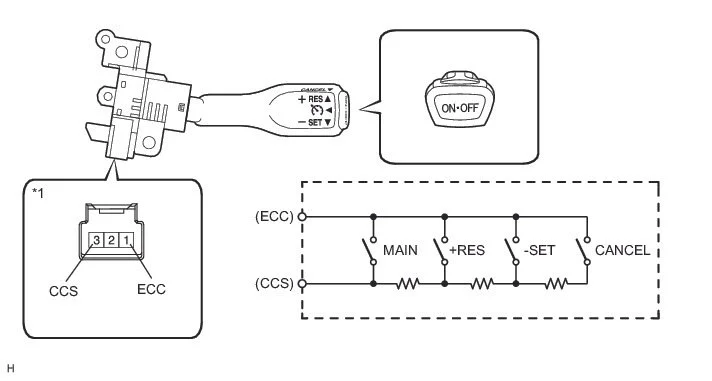
Toyota uses a resistor ladder for the cruise switch. Annoyingly the resisors change from time to time. Find a cruise switch that fits your steering wheel and change the resistors accordingly. I got my cruise control switch from a 2003 MR2 Spyder, since the wheel in my car is also from an MR2 Spyder. There are only two wires on the cruise switch, and due to the resistor ladder, polarity does not matter here. The resistances should be as follows:
NEUTRAL: 1 MΩ or higher
+RES/Accel: 235 to 245 Ω
-SET/Coast: 617 to 643 Ω
CANCEL: 1509 to 1571 Ω
Main Switch: Below 2.5 Ω
If your resistances do not match, replace the resistors inside of your cruise switch with those above.
These will of course have to be run through your clockspring. Pinout does not matter here, just find two suitable open pins. On the other side, connect one wire to ground, and the other to A-40. Again, pinout does not matter here. To verify this behavior, repeat the above resistance test but between ECU ground and A-40.
Conclusion
If you did everything correctly, you now have functional cruise control. Test this at low speeds and verify that pressing your brake and clutch pedals both cancel the cruise control individually. Test that each function of the cruise switch is correct, and now you’re good to go! The only issue currently is that the 2AR ECU does not have a cruise control light output. If you desire this, it can be accomplished with a CAN module which I will not go into here.


