
It’s Not Rocket Surgery
Amidst the gearhead buffoonery, I was still able to accomplish some stuff on the RAV4. One minor hurdle was mounting the pedal. As I’m going with the stock platform ECU on this 1AR, I needed to keep the ethrottle pedal and throttle body, and in fact even if I were going with a standalone I’d still choose ethrottle. It’s just so much better. Anyway, time to find a pedal and mount it.
My first attempt was from a mid 2000s 3MZ-FE Sienna which I had laying around from my 2GR MR2 testing. I did not select that pedal for the MR2, but maybe it’ll work for this. Whip up a few adapters to 3D print and test, and…


It became quickly apparent that this pedal was not going to (easily) work for the RAV4, for some of the same reasons that it didn’t work in my MR2. It is bulky and quickly runs into things that are not easy to shrink. It’s nigh impossible to get the pedal face in the correct location in space with any sort of adapters. This pedal also has a plastic arm which means it is not (easily) modifiable. Back to searching.
No other pedals looked right in the stock configuration, so I took a page out of the Frankenstein Motorworks book and using one of the pedals with a metal arm and making a custom metal arm. Mount the pivot point in any location on the right axis, then put the face wherever you want. I chose a pedal from one of the triplets, but that wasn’t the best idea. But I made it work. Being that those cars came with FA20s, they used Subaru engine computers. The pedal looks like some of the Toyota units, has the same plug, same number of pins, same bolt pattern, both made by Denso. Think they’d work then? Well, for whatever reason, the FRS/BRZ/86 outputs a different signal than what the Toyota ECU wants. Unsurprisingly it’s the Subaru standard ethrottle signals. Luckily, that’s an easy fix. Certain other Toyotas such as some years of Yaris or Prius use that same pedal mount body, while having the position sensor compatible with Toyota signals.

Simple fix really. Sensor swapped right over, and I checked the BRZ pedal afterwards in my MR2 to verify the function. Now knowing that it happily controls the Toyota throttle body, I can proceed with this design. Because I will be making my own pedal arm (and yes I did try the BRZ one stock, didn’t work in any position) I can essentially mount it anywhere there’s clearance and I’m happy with the height. A few 3D Printed tests and some time on the Bridgeport I end up with this.


Yes there may have been some bandsaw work in there too. While I’m not generally a fan of this design, the function really outweighs a lot. For one I don’t like making things unnecessarily strong and heavy, but this material was free and it’s aluminum. I don’t generally like having to line up 3 parts on the same bolt hole, but that means fewer bolts. Believe it or not, that additional slot above the other two bolt holes was deliberate. Some slight futureproofing actually. I’ll be extending the pedal arm a lot over the BRZ. I may find the pedal has too much throw and I might find it annoying to drive. Anyway this bracket was actually designed with that in mind. By flipping the 2 bolt mount upside down, I can actually move the pedal about 50mm lower on the firewall. This would shorten the pedal arm and therefore the overall throw of the pedal. I don’t think I’ll be doing that, but this was an easy thing to add now to give me options. That’s like +5 weight reduction!


Well it actually clears everything this time. I also tried just straightening out the BRZ pedal arm, and it looks like that lines up about perfect. It will take a little more past this, but small victories. Worst case, I now have the two important reference points I need to order a full custom arm. Well that’s crossed off the list at least for now.
Another hurdle I wanted to cross while the engine was in the car was the AC. In a previous post I mentioned how massive the compressor was. Part of that was because the 2AR AC compressors were all variable displacement, which means they could provide a more constant AC pressure, rather than an older off/on system. I don’t really care about that, and that would mean I’d have to wire in a few extra electronics, namely the AC amplifier from a 2AR vehicle, like a RAV4 or a tC. Another Frankenstein Motorworks item, Marc over there sells a bracket to mount the 1ZZ compressor to the 2AR for the Spyder swap. That would knock out two birds for me, for one it would give me a constant displacement compressor, and it would give me more room in front of the engine right by the AC compressor. Only downside to this was that the Spyder has a pretty small compressor, and while the cabin in the RAV4 is not large at all, it is much larger than a Spyder cabin. Looking around, the largest vehicle sold with a 1ZZ was a… RAV4. Over in Europe.
Taking a step back and looking at the compressor, it looks to be a really similar bolt pattern to that of the 2GR. Rough measurements put it in the right spot, and when Toyota reuses nominal dimensions they’re almost always actually identical. The reason I bring this up is that the 2GR has the same issue here, where the AC compressors are variable displacement. The solution for that was to get a compressor from a 1GR-FE Tundra, which was fixed displacement. This allows use of the stock MR2 AC amplifier and wiring. Well I take the gamble and purchase (another) Tundra compressor. Worst case I keep it around as a spare for the MR2. Denso 471-1012.

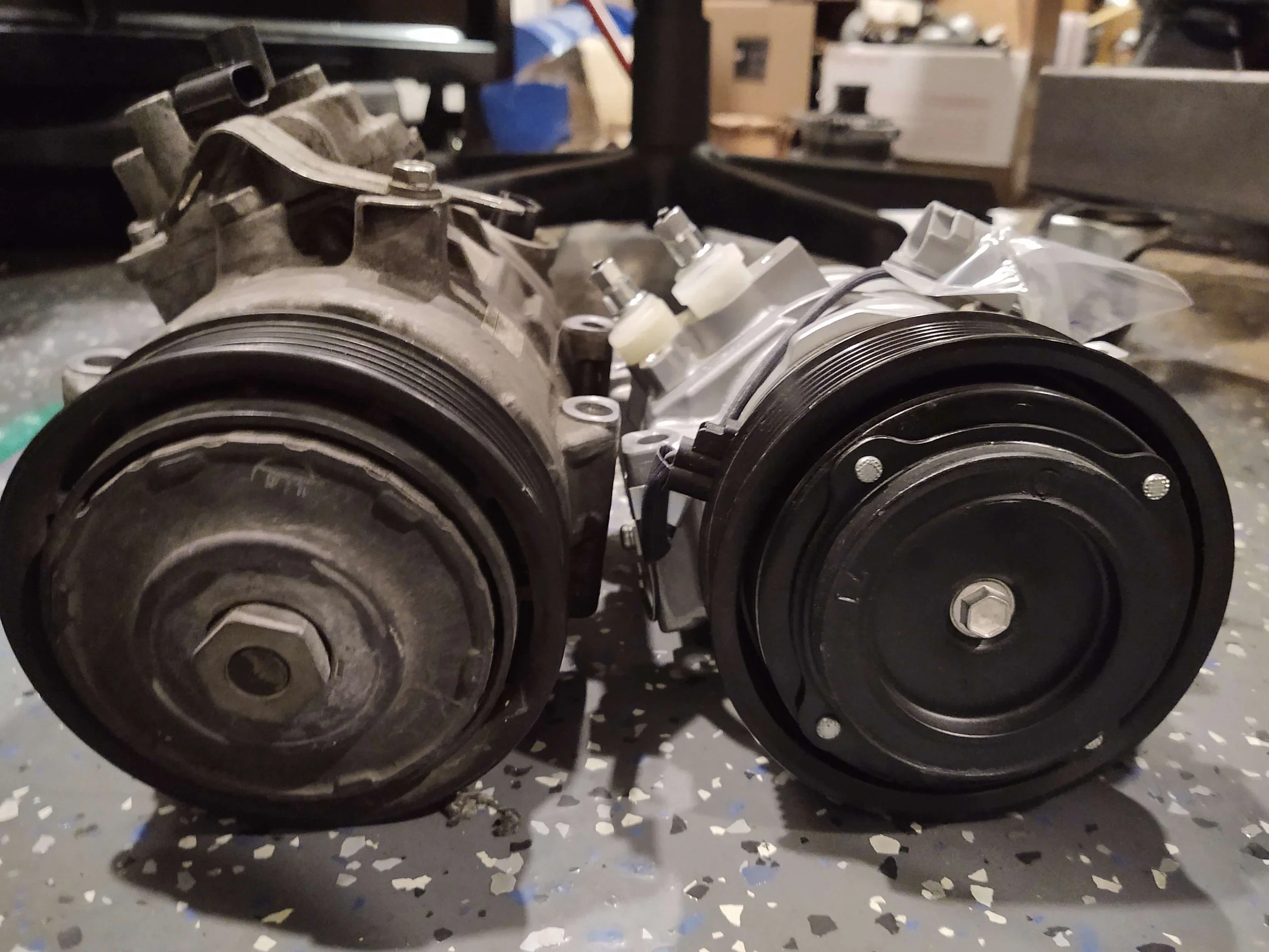
Well those bolt patterns sure look similar. And that Tundra compressor is way smaller.


Holy crap, not only does it fit, it adds an immense amount of room. This also means that the existing AC solutions for 2GR SW20s will work for 2AR SW20s. Neat!
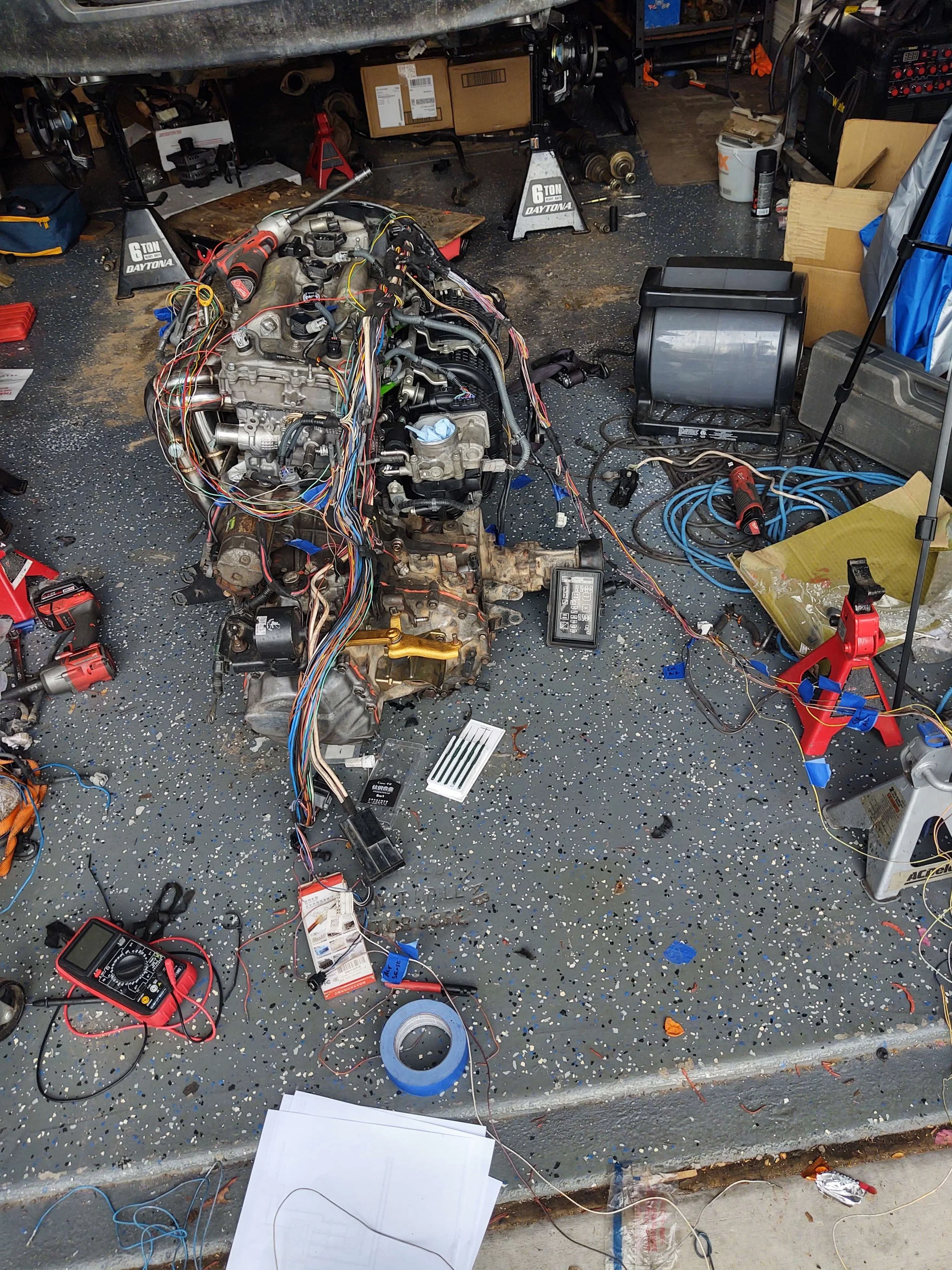
Wiring.
Everyone loves wiring.
I’m going through approximately the same process that I had done for my SW20. What I did with that car (and now this car) is that I did not modify anything that touched the transmission. Because I’m not replacing the transmission, there’s no reason to rewire all of that again. I cut off anything that had to do with 3SFE engine control, such as the injectors, coil, various sensors, everything. This may take some extending wires after the fact due to routing the harness differently, but that will be an easier bridge to cross than a full rewire.

What I’m keeping vs. what I’m tossing
I got everything stripped down to being a “standalone transmission harness” and then proceeded to do the opposite on the 2AR harness. Luckily, the 2AR harness has very little in terms of transmission control since my harness came from a manual transmission vehicle. Modern Toyotas don’t have vehicle speed sensors in the transmission, they get speed signals from the ABS ECU. I don’t care, fewer wires to remove. The primary items to deal with are the starter and alternator wires. The battery on the tC is on the opposite end of the bay from my RAV4, so they are nowhere near lining up. I can keep the stock alternator wire from the RAV4 harness, and tie that into the 2AR harness.

Cleaning dirty laundry.
Most of the integration will actually be done with the engine outside of the car. I already have correct lengths for the bits that go to the chassis sides, so if I just follow those then I should be fine. One major issue that I have to solve is the ECU plug. On the tC and I believe all of the other 2AR cars (and most Toyotas in general) have the ECU mounted in the engine bay, typically right by the airbox. This is not normally a problem, but I would prefer my ECU to be in the cabin. Given the use case there is a solid chance of this engine bay getting submerged completely. Anyway, without making more holes on the RAV4 firewall, I need to move the ECU plug to the opposite end of the engine. Because of the above, the 2AR ECU plug is right above the transmission, and the RAV4 firewall hole is right by the timing cover. Cool.
With both harnesses stripped of all loom and sheathing, it was time for integration. Luckily, Toyota does not often rename signals. This made for a pretty simple process of checking two wiring diagrams back and forth to find what needs to go where. Again, luckily, a lot of the positions of things on the tC harness end up in almost the same location as where they need to go on the RAV4 harness. Furthermore, Toyota being Toyota, almost every signal that needed to be moved over used the exact same terminal as the receiving RAV4 connector. This made the process as simple as a depin, move, repin. The process only got slightly more complicated with moving the ECU plug. One small goal I had was that I didn’t want to extend any shielded wires. I didn’t have any on hand, so that was just one part I didn’t want to deal with. The O2s, crank sensor, knock sensor, and throttle body motor are the shielded wires to keep in mind. I realized that I would have to extend the throttle, so I sucked it up and cut those wires. The next closest shielded wire was the knock sensor, so I tried keeping that one. I cut any wires that were hung up, and basically “folded” the ECU leg over itself to point the other direction. This appeared to be the right length, and left me with 15 or so wires to extend. Both cam sensors, coils and injectors for cylinders 3 and 4, ECT, and throttle body. The remaining connectors to extend are the MAF and the purge solenoid, and due to me not knowing exactly where those will land, I’ll have to wait until those items are fabricated in the car. Minor change at this time, the 3 pin sensor commonly used on 2gr swaps also fits here, sensor PN 84922-22030 and connector PN 90980-11451. Pins 1 and 2 stayed the same, pin 3 was moved over from the stock RAV4’s temp sensor.


Next thing on the list to knock out was the 4wd sensor. I cut the connector off the top to have clearance to the 1AR-FE intake manifold, then soldered wires to the terminals and epoxied them in place. Easy peasy, ran the wires to a different connector and it works.
On that note, I wanted to actually mount the connector and not just have it hanging around. I originally intended to p-clamp it but I realized I had an easy location nearby.


Threw this together to print out and epoxy, that way the connector is rigidly mounted to something and actually indexes properly as to not rotate. In case anyone is following along, this file will be added to the “Printables” section on this website.
With all of the wiring that I can finish outside the car done, it’s time to mount the engine in the car, hopefully for the last time. While I had it ready, I decided to weigh the drivetrain assembly.


A hair under 500lb for everything? Oink. This was everything but the wiring harness. I weighed it in a few other configurations for comparison sake:
Everything: 499lb
Header, intake, starter removed: 463lb
Engine (Bare, clutch+flywheel): 285lb
Transmission: 178lb
With that out of the way, time for the actual install.


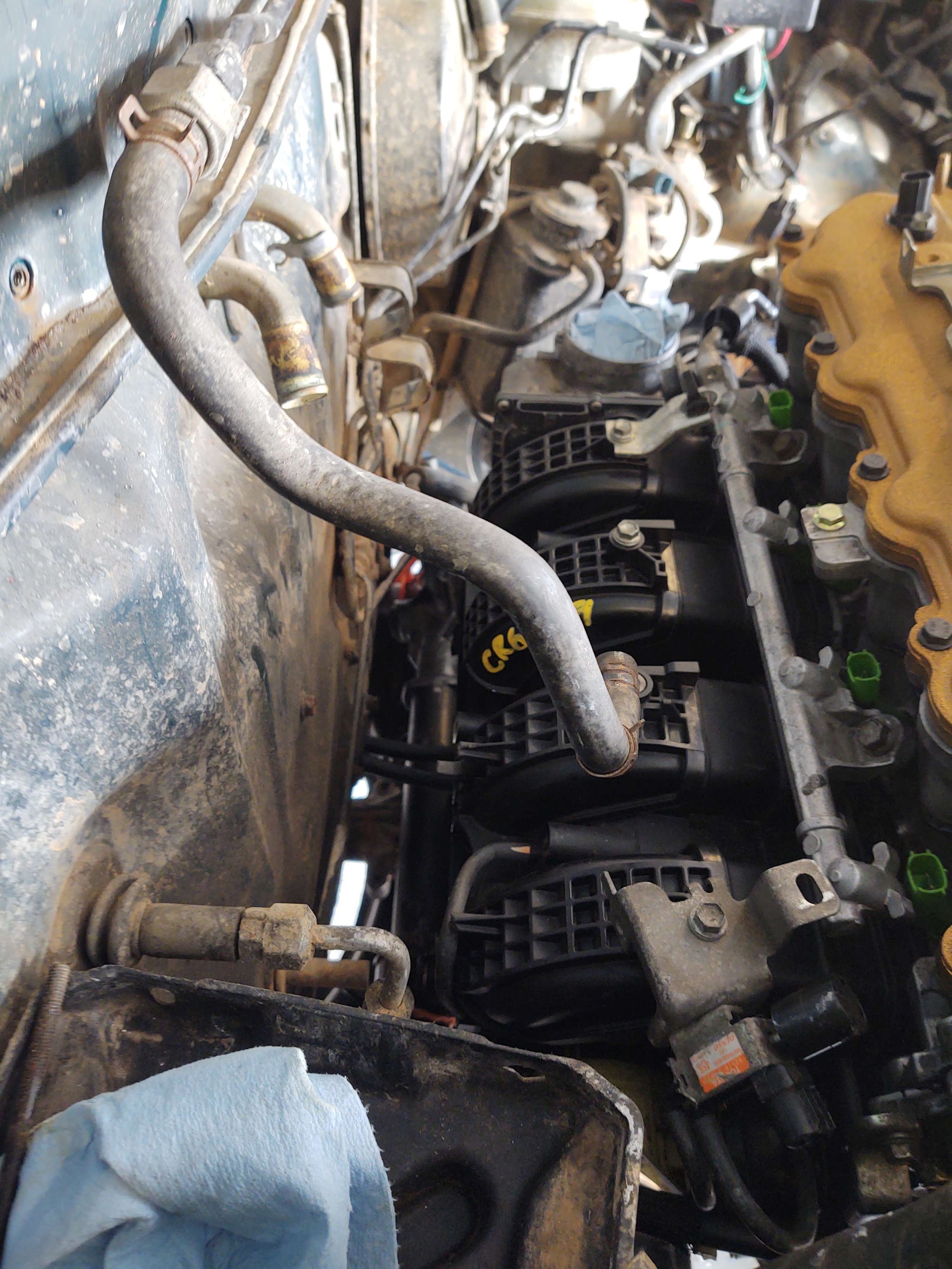


Well, everything went smoothly. The mounts lined up, the intake fit (this was actually my first time testing that), there’s clearance everywhere, it fits really dang well in the bay. I honestly think it’s done. Got all of the suspension back on the car, and set it down on the ground. It’s a little surreal seeing it on the ground again, after being on jackstands for 177 days. With that, it’s a good stopping point. What’s left is to make the intake and exhaust, finish/tidy up wiring, plumb the coolant, and make AC lines. Those are all significant levels of fabrication, but they are attainable. I had always planned to go with an electronic power steering setup, and while I still have the parts to make that happen, this was surprisingly easy to turn on without it. I may skip that part of the build, but I may change my mind again if I get larger tires.
Continuous improvement.